


MINI REED SWITCH
General Description:
Mini Reed switches are mechanical devices that are triggered by a magnet, causing the magnetic field to pull the metallic switch contacts together. These switches are valued for their compact size, low power consumption, and reliability.
Working Principle:
A mini reed switch operates using two ferromagnetic reeds sealed in a small glass tube. In its resting state, the reeds are separated, keeping the switch open. When an external magnetic field is applied, the reeds become magnetized and attract each other, closing the switch and allowing current to flow. Removing the magnetic field causes the reeds to demagnetize and separate, opening the switch and stopping the current flow. This mechanism ensures precise and reliable switching without physical contact with the actuating magnet.
Specifications:
1. Operates within a range of 3.3V to 5V.
2. Output is digital, meaning the switch provides a clear ON/OFF signal.
Requirements
| S. No. | Component Name | Values |
|---|---|---|
| 1 | Resistors | 1K,220R, 10k |
| 2 | LED | |
| 3 | MMBT100 (Bipolar Transistors) | |
| 4 | MATE-12B-10-15 (Reed Switch) | |
| 5 | Male pin connector | 4 |
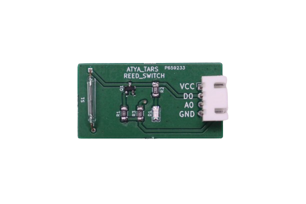
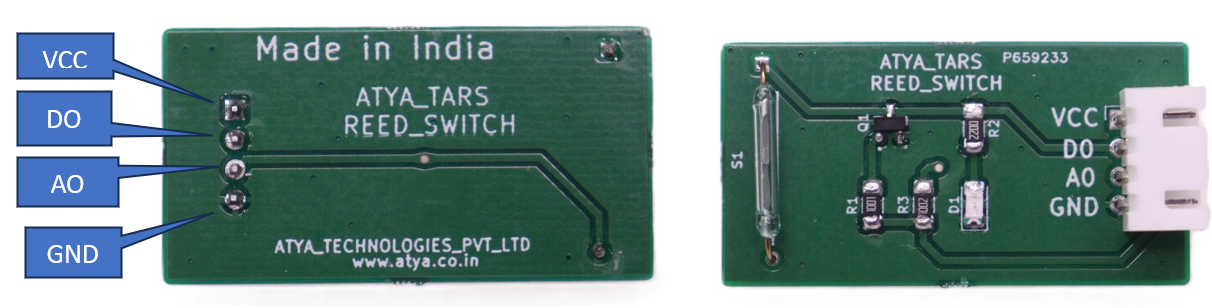
Pin configuration:
| S. No. | Pins | Pin Description |
|---|---|---|
| 1 | VCC | 5V |
| 2 | D0 | digital pin |
| 3 | A0 | analog pin |
| 4 | GND | digital clock pin |
Pin Diagrams:
Applications:
1. Automotive industries utilize mini reed switches for monitoring door positions and seatbelt status.
2. Used in mechanical systems as proximity sensors.
3. Used for position detection in production processes, as well as the measurement of tank levels in the chemical, pharmaceutical, and food industries.
4. Used in medical devices where they detect movable parts or assist in patient positioning.
For more info: Refer the Datasheets!
TILT SENSOR
General Description:
A Tilt Sensor, also known as a Tilt Switch, detects the orientation of an object, though it doesn't measure the angle of tilt as accelerometers do. Instead, it indicates whether the sensor is tilted or not.
A Mercury switch-based tilt sensor module outputs high when tilted, requiring a 5V DC input. It typically has three terminals: input, ground, and output. Inside, there's a glass tube with two electrodes and a liquid mercury ball. When the sensor is tilted in a particular direction, the mercury ball moves, opening or closing the circuit.
Working Principle:
Tilt sensors are made up of a plastic or glass tube, with two pieces of wire and a metal ball inside:

When the tube is tilted forward, the ball rolls forward and only contacts one wire.
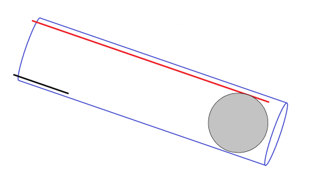
When the tube is tilted backward, the ball rolls back and contacts both wires.
This allows current to flow between the two wires. We can detect this high or low signal with the Arduino to determine if the sensor is tilted or not.
Specifications:
1. Tilt sensor consists of 3 pins: GND, VCC, DO (Output Signal).
2. Operating Voltage: 3.3 V to 5 V.
3. Maximum output current: 15mA.
4. Output Type: Digital.
5. Tilt Angle Threshold: Typically, around 45° (can vary depending on model).
Requirements
| S. No. | Component Name | Values |
|---|---|---|
| 1 | Resistors | 470R |
| 2 | LED | |
| 3 | Tilt Sensor |
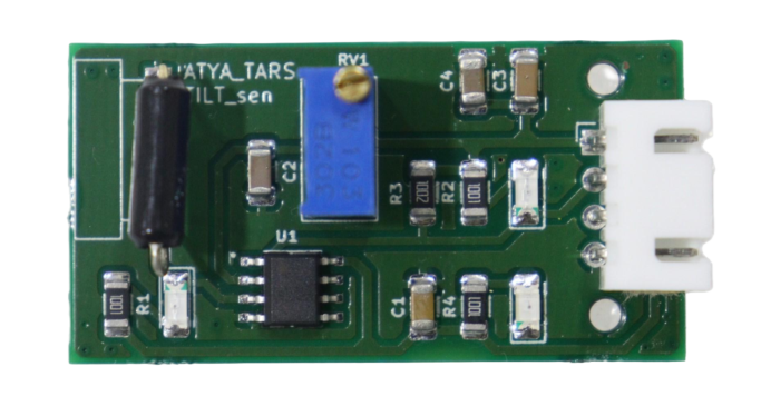
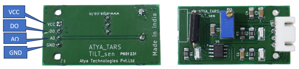
Pin configuration:
| S. No. | Pins | Pin Description |
|---|---|---|
| 1 | S | Output Digital Pin |
| 2 | VCC | 3.3V - 5V |
| 3 | GND | Common Ground |
Pin Diagrams:
Applications:
1. Interactive Games and Toys.
2. Security and Alarm Systems.
3. Automation and Robotics.
4. Art installations and Displays.
For more info: Refer the Datasheets!
HALL EFFECT SENSOR

General Description:
The Linear magnetic Hall sensor reacts in the presence of a magnetic field. It has a potentiometer to adjust the sensitivity of the sensor and it provides both analog and digital outputs. The digital output acts as a switch that will turn on/off when a magnet is near. On the other hand, the analog output can measure the polarity and relative strength of the magnetic field.
Working Principle:
Hall Effect sensor module is used to detect the proximity of a magnet. It is much smaller in size, when the magnetic field rises above a threshold level, the open collector output transistor switches on, which pulls the logic-compatible output low and illuminates the onboard LED indicator.
Specifications:
1. Voltage comparator LM393.
2. Adjustable sensitivity.
3. Output from digital switch output (0 and 1).
4. Signal output indication.
5. Single channel signal output.
6. The output effective signal is low level.
7. When there is sound, outputs low level and the signal light.
Requirements
| S. No. | Component Name | Values |
|---|---|---|
| 1 | IC LM393(Op-Amp) | |
| 2 | Resistors | 150R,1K,10K,100K |
| 3 | Potentiometer | 100K |
| 4 | LED'S | |
| 5 | 3-terminal Hall Effect Sensor | |
| 6 | Male Connectors | 4 |
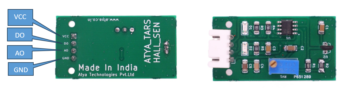
Pin configuration:
| S. No. | Pins | Pin Description |
|---|---|---|
| 1 | D0 | Digital output pin |
| 2 | VCC(+) | Input Voltage 3.3-5v |
| 3 | GND | Common Ground |
| 4 | A0 | Analog output pin |
Pin Diagrams:
Applications:
1. Motor speed measurement.
2. Object position detection.
3. Smart car.
4. Electronic bricks.
For more info: Refer the Datasheets!
DETECTING SENSOR RELAY MODULE
General Description:
It is a fire flame detection sensor relay Module. The flame sensor can detect the flame or the wavelength at 760 nm to 1100 nm range of the light source, the test flame lighter distance of 80cm, the larger the flame, the greater the distance test. The detection angle of 60 degrees, and the flame spectrum is particularly sensitive. Sensitivity is adjustable (shown in blue digital potentiometer adjustment). The comparator output directly triggers the relay. The output bluish Terminal Block for convenient connections.
Working Principle:
A fire flame-detecting sensor relay module operates by utilizing a flame sensor to detect infrared radiation emitted by flames. When flames are detected, the sensor triggers a relay, which can activate alarms, shut down equipment, or initiate other safety measures. These modules are essential components in fire detection and safety systems, providing early warning and helping to prevent potential hazards. Regular calibration and integration into larger safety systems ensure their effectiveness in various environments.
Specifications:
1. Having an IC chip LM393 voltage comparator.
2. Operating Voltage (VDC) is 3V-5V.
3. Max voltage for the relay is 250V AC and turned on by a 5V supply (on logic).
4. Operating current 150mA.
5. Mounting holes to facilitate fixed installation.
6. It has the signal output indicating LED.
7. Operating Distance Range is 0.8 meters.
8. Long working life and stable performance.
9. Relative Humidity is 20% -85%.
10. Operating Temperature: -40°C to 80°C.
Requirements
| S. No. | Component Name | Values |
|---|---|---|
| 1 | LM393 (Voltage Comparator) IC | |
| 2 | Phototransistor (flame sensor) | |
| 3 | Resistors | 472R |
| 4 | Capacitors | 106,104,105(n) |
| 5 | Male connectors | 2 |
| 6 | Variable potentiometer | 10k |
| 7 | Indication LEDs | |
| 8 | Zenor diode | |
| 9 | Terminal Block | 3 |
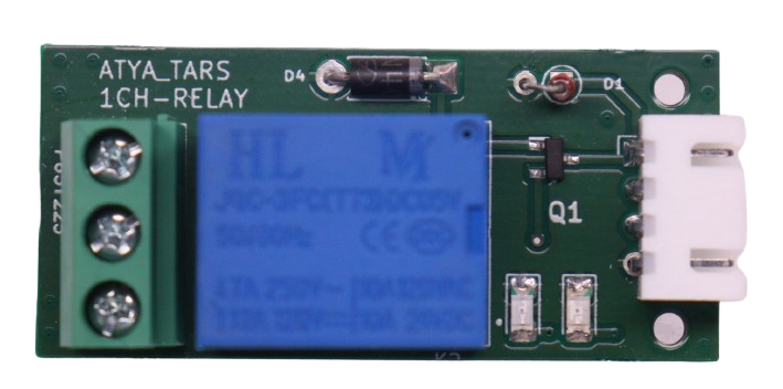
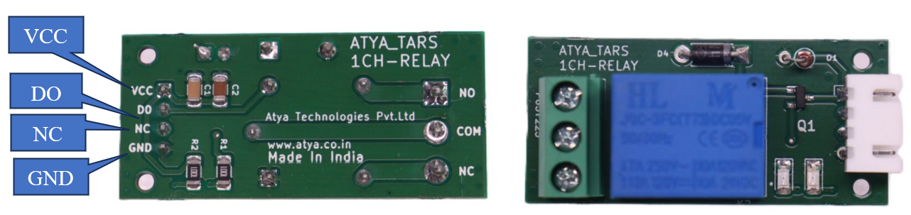
Pin configuration:
| S. No. | Pins | Pin Description |
|---|---|---|
| 1 | VCC | Input voltage (3V to 5V) |
| 2 | GND | ground |
| 3 | NC | Normally closed relay pin |
| 4 | NO | Normally opened relay pin |
| 5 | CN | Common AC port |
Pin Diagrams:
Applications:
1. Industrial Facilities.
2. Commercial Buildings.
3. Residential Settings.
4. Environmental Monitoring.
5. Transportation.
6. Energy and Power Plants.
For more info: Refer the Datasheets!
SLIDE SWITCH
General Description:
A slide switch is a type of bistable switch with two stable positions that control the flow of current in a circuit. It can be toggled between open and closed positions by sliding its actuator. These switches will stay in one position until changed into another position manually. A slide switch can also be used to connect two further circuits to an existing one and to connect them optionally.
Working Principle:
The working principle of a slide switch revolves around its internal mechanism of movable metal contacts within a housing. When the actuator or slider is moved, it physically shifts these contacts to either make or break electrical connections. In the closed position, the contacts come into contact, allowing current to flow through the switch and complete the circuit. Conversely, in the open position, the contacts are separated, interrupting the current flow. It's this straightforward functionality that makes slide switches a popular choice for many devices.
Specifications:
1. It has a current rating of 25mA.
2. Can handle up to 24VDC of voltage.
3. The actuator type is a Slide (Standard) and actuator level is raised.
4. Contacts are made from copper alloy with a gold finish.
5. It is designed for operation in temperatures ranging from -40°C to 85°C.
6. Its body is made from Polybutylene Terephthalate (PBT).
7. Termination style is PC pin with a pitch of 0.100 inches (2.54mm).
Requirements
| S. No. | Component Name | Values |
|---|---|---|
| 1 | Resistors | 100R |
| 2 | Slide switch | |
| 3 | Male pin connector | 4 |
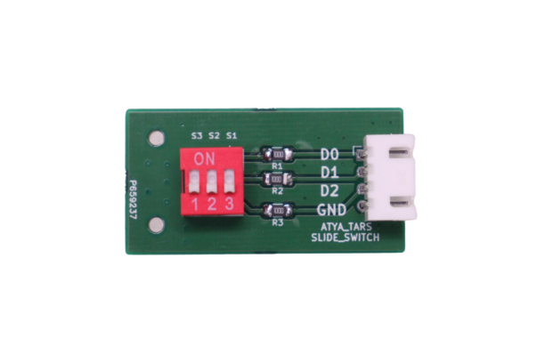
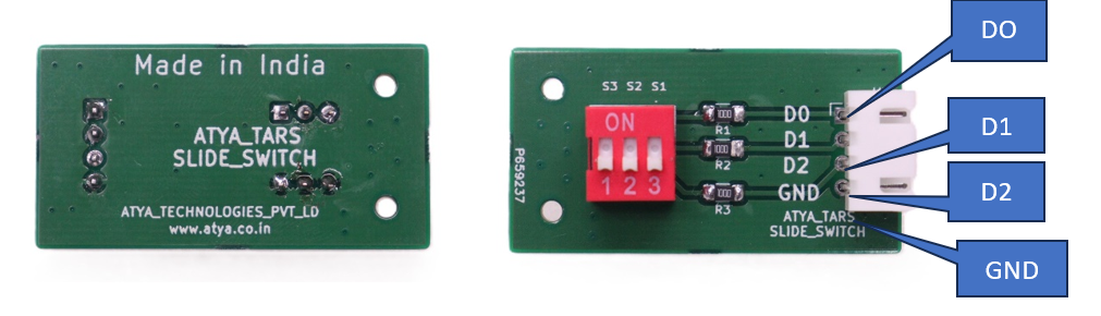
Pin configuration:
| S. No. | Pins | Pin Description |
|---|---|---|
| 1 | D0 | digital pin |
| 2 | D1 | digital pin |
| 3 | D2 | digital pin |
| 4 | GND | ground |
Pin Diagrams:
Applications:
1. Slide switches are often used to turn flashlights on and off.
2. Found in dashboards and control panels for operating lights, wipers, and other vehicle functions.
3. They're also used in more industrial applications to control electrical circuits in machinery or equipment.
4. Used in devices like small radios, portable music players and other consumer electronics.
For more info: Refer the Datasheets!
TOUCH SENSOR
General Description:
The touch sensor module is a type of switch that only operates when it's touched by a charged body. It has a high-frequency transistor that can conduct electricity when receiving electromagnetic signals. The Metal Touch Sensor Module utilizes a floating lead on a Darlington transistor to detect a touch.
Working Principle:
Metal Touch Sensor Module is an analog/digital sensor that uses a transistor to detect changes in electrical conductivity. When the transistor is touched with a finger, the conductivity changes, and the module emits a digital and analog signal. The digital output can be used as a switch that changes state when touched. The analog output can measure the intensity of the touch. The detection threshold can be regulated using the on-board potentiometer.
Specifications:
1. Operating voltage: 3.3 ~ 5.5V DC.
2. Adjustable sensitivity.
3. The output type is analog as well as digital.
4. Single-channel signal output.
5. Detects the presence of metal nearby.
Requirements
| S. No. | Component Name | Values |
|---|---|---|
| 1 | LM393 (OP-AMP) | |
| 2 | Resistors | 150R,1K,10K,100K |
| 3 | Variable Potentiometer | 100K |
| 4 | LED'S | |
| 5 | Male Connector pin | 4 |
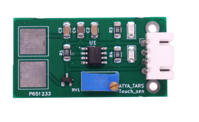
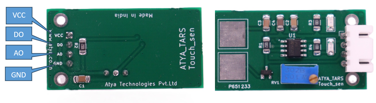
Pin configuration:
| S. No. | Pins | Pin Description |
|---|---|---|
| 1 | A0 | Analog output pin |
| 2 | GND(G) | Connect to ground |
| 3 | VCC (+) | Input Voltage: 3.3-5V |
| 4 | D0 | Digital output pin |
Pin Diagrams:
Applications:
1. Used for screening purposes in malls, airports, and stations.
2. Food processing industry.
3. Home appliances.
4. Cellular handsets.
5. Portable media devices.
For more info: Refer the Datasheets!
CAPACITIVE TOUCH
General Description:
Touch Sensor is an ideal product for you. It enables you to replace the press with touch. It comes with an LED to indicate the touch. Using the TTP223-B touch detector IC, it measures the capacitance of a metallic pad and detects the change in capacitance when a finger is touched near it, so you can place the metallic pad under a non-metallic surface such as a plastic or glass sheet and it will work as a button. This is the same technology used in the touch screens of iPhones
Working Principle:
The TTP223-BA6 operates through capacitive sensing, detecting changes in capacitance when a conductive object approaches its touch-sensitive pad. With an internal oscillator, it continuously monitors frequency variations caused by proximity. Upon detecting a touch event, it produces a digital output signal, offering reliability through internal debouncing circuitry. Configurable for sensitivity and timing, it provides a simple and efficient solution for implementing touch-sensitive controls in diverse electronic applications.
Specifications:
1. Chipset Used: TTP223-BA6 touch detection IC.
2. Output Response Time: 60 - 220ms.
3. Operating Voltage 2.0-5.5V.
Requirements
| S. No. | Component Name | Values |
|---|---|---|
| 1 | TTP223-BA6 IC (Touch detection IC) | |
| 2 | Touchpad (On PCB board) | |
| 3 | Resistors | 472R |
| 4 | Capacitors | 106,104,105(n) |
| 5 | Male Connector pin | 4 |
| 6 | LEDs |
Pin configuration:
| S. No. | Pins | Pin Description |
|---|---|---|
| 1 | GND | ground |
| 2 | VCC | Input voltage (2V to 5.5V) |
| 3 | NC | No connection |
| 4 | SIG | Analog/Digital Pin |
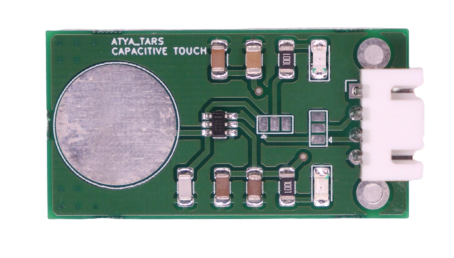
Pin Diagrams:

Applications:
1. Various electronic devices such as Smartphones, tablets, touch-sensitive.
2. Coffee makers.
3. Microwave ovens etc.
For more info: Refer the Datasheets!