

ULTRASONIC SENSOR
General Description:
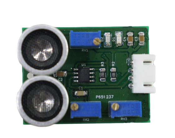
An ultrasonic sensor measures distance by emitting ultrasonic sound waves and analyzing the echoes received from objects. The HC-SR04, a popular and cost-effective sensor, has a range from 2cm to 400cm (about an inch to 13 feet). It consists of two ultrasonic transducers: a transmitter that sends out ultrasonic pulses and a receiver that detects the reflected waves. This functionality resembles SONAR used in submarines to detect underwater objects.
Working Principle:
The Ultrasonic (US) sensor, featuring pins Vcc, Trigger, Echo, and Ground, is widely used for distance measurement and object detection. It comprises an ultrasonic transmitter and receiver. The transmitter converts electrical signals into 40kHz sonar wave bursts upon receiving a 10µs pulse trigger. These waves bounce off objects and return to the sensor.
Utilizing the formula Distance = Speed * Time, where the speed of sound in air is approximately 330m/s, the sensor calculates the distance by measuring the time taken for the wave to return. This is done by activating the echo pin high for the same duration. The sensor's built-in circuitry simplifies distance calculation, making it suitable for use with microcontrollers or microprocessors.
Specifications:
1. Operating voltage: +5V
2. Theoretical Measuring Distance: 2cm to 450cm
3. Practical Measuring Distance: 2cm to 80cm
4. Accuracy: 3mm
5. Measuring angle covered: 15°
6. Operating Current: 15mA
7. Operating Frequency: 40Hz
Requirements
| S. No. | Component Name | Values |
|---|---|---|
| 1 | LM324 IC (OP-AMP) | 2 |
| 2 | MAX3232 IC (Transceiver) | |
| 3 | Resistors | 10kΩ,20 kΩ,220Ω,1 kΩ 330Ω |
| 4 | Capacitors | 0.1μF,10 μF, 10nF, 100nF |
| 5 | Male Connector pin | 4 |
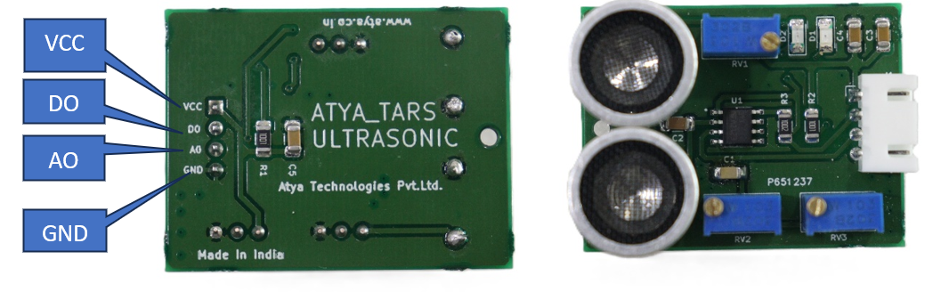
Pin configuration:
| S. No. | Pins | Pin Description |
|---|---|---|
| 1 | VCC | The Vcc pin powers the sensor, typically with +5V |
| 2 | Trigger | The trigger pin is a digital Input pin. This pin has to be kept high for 10us to initialize measurement by sending a US wave. |
| 3 | Echo | The echo pin is a digital Output pin. This pin goes high for a period that will be equal to the time taken for the US wave to return to the sensor. |
| 4 | Ground | This pin is connected to the Ground of the system. |
Pin Diagrams:
Applications:
1. Used to avoid and detect obstacles with robots like biped robots, obstacle avoider robots, path-finding robots, etc.
2. Used to measure the distance within a wide range of 2cm to 400cm
3. Can be used to map the objects surrounding the sensor by rotating it
4. Depth of certain places like wells, pits, etc can be measured since the waves can penetrate through water
For more info: Refer the Datasheets!