


BUZZER
General Description:
A buzzer module is an electronic component used to generate sound. It typically consists of a piezoelectric or electromagnetic buzzer, which converts electrical signals into audible tones. The module can operate in either active or passive modes:
1.Active Buzzer: Contains an internal oscillator that generates sound when powered by a DC voltage. It continuously emits a tone without needing an external signal.
2.Passive Buzzer: Lacks an internal oscillator and requires an external signal, such as a square wave from a microcontroller, to produce sound.
Working Principle:
The working principle of the passive buzzer module is based on the piezoelectric effect. When an electrical signal is applied to the buzzer, it causes a piezoelectric crystal inside the buzzer to vibrate at a specific frequency. This vibration produces sound waves that we can hear. The frequency of the sound produced by the buzzer depends on the frequency of the electrical signal applied to it. By changing the frequency of the signal, we can change the pitch of the sound produced by the buzzer.
Specifications:
1. Operating Voltage : 1.5 ~ 15V DC.
2. Working Current: Less than 25mA.
3. Tone Generation Range : 1.5 ~ 2.5kHz.
Requirements
| S. No. | Component Name | Values |
|---|---|---|
| 1 | Buzzer | |
| 2 | Resistor | 220R |
| 3 | Male pin connector | 4 |
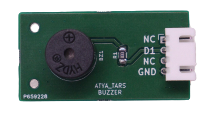
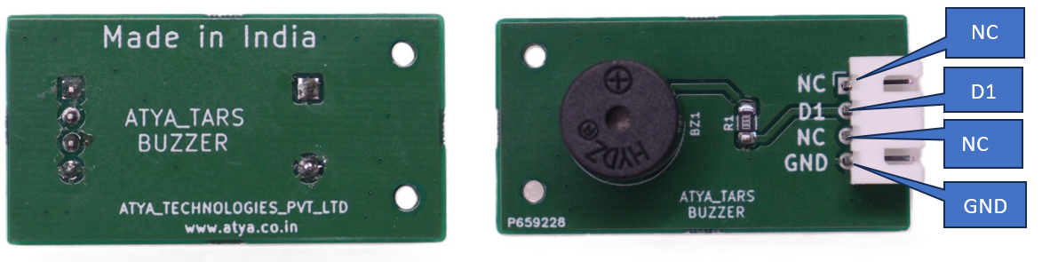
Pin configuration:
| S. No. | Pins | Pin Description |
|---|---|---|
| 1 | NC | Not connected pin |
| 2 | D1 | digital pin |
| 3 | NC | Not connected pin |
| 4 | GND | ground |
Pin Diagrams:
Applications:
1. Fire alarms.
2. Security systems.
3. Microwave ovens.
4. Automotive seatbelt reminders.
5. Industrial machinery status alerts.
For more info: Refer the Datasheets!
INFRARED
General Description:
An Infrared emitter, or IR emitter, is a source of light energy in the infrared spectrum. This little part is a light emitting diode (LED) that is used in order to transmit infrared signals from a remote control. This simple device operates at 940nm and works well for generic IR systems. This emitter is driven up to 50mA with a current limiting resistor as with any LED device.
Working Principle:
The IR emitter, or infrared emitter, works by converting electrical energy into infrared radiation. This radiation is in the infrared spectrum, which is not visible to the human eye but can be detected by infrared sensors. The emitter typically consists of a semiconductor material that emits infrared light when current flows through it. This emitted light can be used for various applications such as remote controls, proximity sensors, and infrared communication.
Specifications:
1. Continuous Forward Current: 50mA.
2. Reverse Voltage: 5V.
3. Operating Temperature: -25~+85°C.
4. Wavelength: 940nm.
5. Voltage - Forward (Vf) (Typ): 1.2V.
Required Components:
| S. No. | Component Name | Values |
|---|---|---|
| 1 | IR LED | |
| 2 | Resistors | 100R,1k |
| 3 | MMBT100 | |
| 4 | LED | |
| 5 | Male connector pin | 4 |
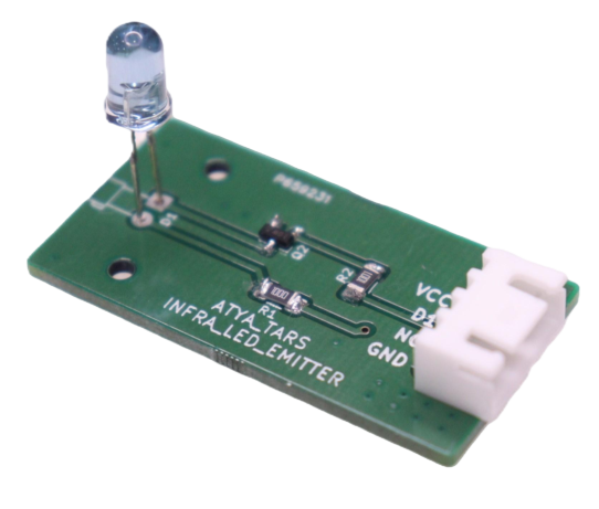
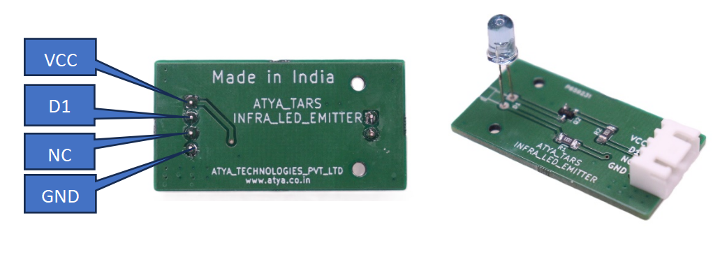
Pin configuration:
| S. No. | Pins | Pin Description |
|---|---|---|
| 1 | VCC | +5V |
| 2 | D1 | Digital pin |
| 3 | NC | No Connection |
| 4 | GND | ground |
Pin Diagrams:
Applications:
1. Infrared communication.
2. Object detection.
3. Optical encoders.
4. Infrared heating.
5. Spectroscopy.
For more info: Refer the Datasheets!
LED
General Description:
A light-emitting diode (LED) is a semiconductor device that emits light when an electric current flows through it. When current passes through an LED, the electrons recombine with holes emitting light in the process. LEDs allow the current to flow in the forward direction and blocks the current in the reverse direction.
Working Principle:
LEDs, or Light Emitting Diodes, work based on the principle of electroluminescence. When a voltage is applied to the LED, current flows through the semiconductor material, causing electrons to recombine with electron holes within the device, releasing energy in the form of photons, which produces light.
Specifications:
1. Very cheap.
2. Come in different shapes, sizes, and colors.
3. RGB LEDs allow you to light them up in virtually any color.
4. Light up very quickly.
5. Physically robust.
6. Can easily be dimmed by lowering the forward current or with PWM.
7. Radiate very little heat.
8. Long lifetime.
9. Can be used in a variety of applications.
Required Components:
| S. No. | Component Name | Values |
|---|---|---|
| 1 | LED | |
| 2 | Resistors | 330R |
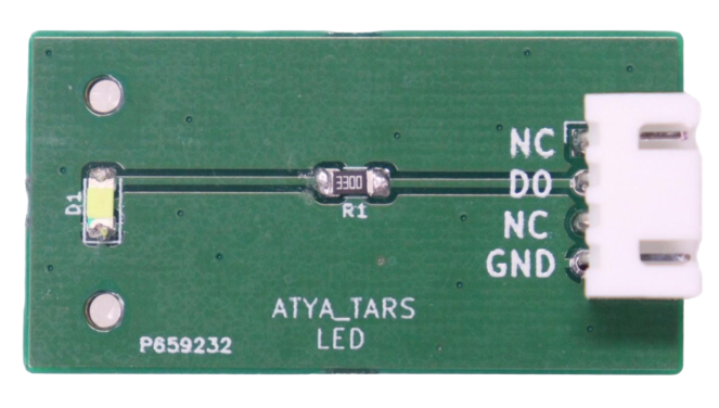
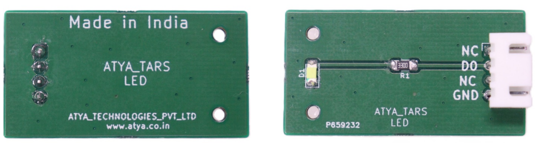
Pin configuration:
| S. No. | Pins | Pin Description |
|---|---|---|
| 1 | NC | No Connection |
| 2 | D0 | Digital pin |
| 3 | NC | No Connection |
| 4 | GND | ground |
Pin Diagrams:
Applications:
1. Indicator lights.
2. Displays.
3. Automotive lighting.
4. Backlighting, and general lighting.
For more info: Refer the Datasheets!
PUSH BUTTON
General Description:
A push-button, also known simply as a button, is a basic switch mechanism used to regulate aspects of a machine or process. The module is designed for two contacts: when pressed, they are closed and open when released. These buttons are commonly made out of hard material, usually plastic or metal. These switches are widely used in electronic devices, machinery, and control systems for their ease of operation and reliability in initiating commands or processes.
Working Principle:
Push button switches operate through a spring mechanism that compresses and releases internal contacts when the button is pressed. This allows the contacts to touch each other and complete an electrical circuit. Upon release, the spring returns the button to its original position, separating the contacts and breaking the circuit to stop the function.
Specifications:
1. It operates at 5 volts DC.
2. It maintains a low contact resistance of ≤50 million ohms.
3. It has a temperature tolerance spanning from -25°C to 105°C.
4. Its mechanical and electrical lifecycle is rated for approximately 100,000 cycles.
Requirements
| S. No. | Component Name | Values |
|---|---|---|
| 1 | Resistor | 220R |
| 2 | Push button | |
| 3 | Male pin connector | 4 |
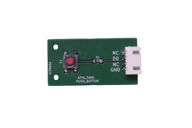
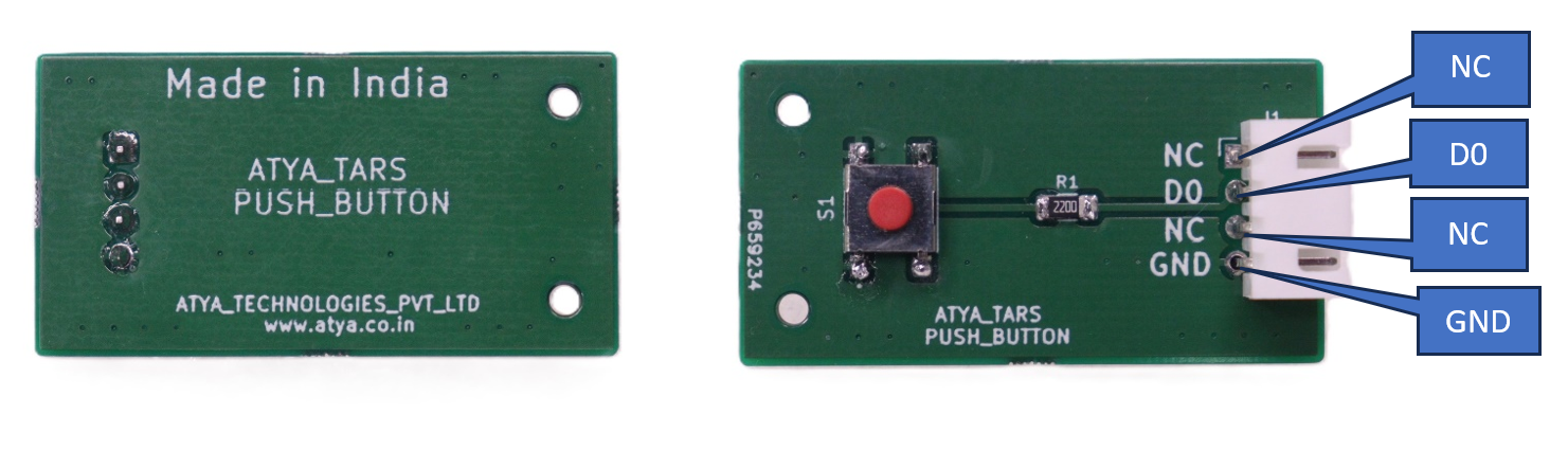
Pin configuration:
| S. No. | Pins | Pin Description |
|---|---|---|
| 1 | NC | Not connected pin |
| 2 | D1 | digital pin |
| 3 | NC | Not connected pin |
| 4 | GND | ground |
Pin Diagrams:
Applications:
1. For automotive horns and door jam switches.
2. Electronic devices: As control inputs to start and stop motors or turn devices on and off.
3. They are used in consumer electronics, industrial control systems, and communication devices.
4. Integrated into devices for user interface control, such as digital cameras, handheld consoles, and remote controls.
For more info: Refer the Datasheets!
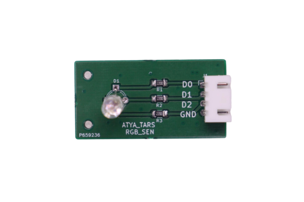
RGB LED
General Description:
An RGB LED is a type of light-emitting diode that can emit light in three primary colors: red (R), green (G), and blue (B). By adjusting the intensity of each color component, a wide range of colors can be produced. These LEDs are commonly used in various applications where colorful lighting effects are desired.
Working Principle:
The working principle of an RGB LED involves three separate semiconductor chips within a single package, each emitting red, green, or blue light when current passes through. By varying the intensity of each color using pulse-width modulation (PWM), the LED can create a wide spectrum of colors by mixing these primary colors. For instance, activating only the red light source results in a red glow, while combining red and green produces yellow because these colors mix to form yellow light. This process of mixing different intensities of red, green, and blue light sources enables RGB LEDs to generate a wide range of colors, demonstrating the fundamental principle of color mixing in light.
Specifications:
1. Low Thermal Resistance.
2. No UV rays emitted.
3. Super High flux Output and High luminance.
4. Forward Current for Red, Blue and Green color: 20mA.
5. Forward Voltage: 1.Red: 2V (typical) 2.Blue: 3.2V (typical) 3.Green: 3.2V (typical).
6. Luminous Intensity: 1.Red: 800 mcd 2.Blue: 4000 mcd Green: 900 mcd.
7. Wavelength: 1.Red: 625 nm 2.Blue: 520 nm 3.Green: 467.5 nm.
8. Operating Temperature ranges from 25°C to 85°C.
Requirements
| S. No. | Component Name | Values |
|---|---|---|
| 1 | Resistor | 220R |
| 2 | RGB | |
| 3 | Male pin connector | 4 |
Pin configuration:
| S. No. | Pins | Pin Description |
|---|---|---|
| 1 | D0 | digital pin |
| 2 | D1 | digital pin |
| 3 | d2 | digital pin |
| 4 | GND | ground |
Pin Diagrams:

Applications:
1. Commonly used component in electronics, generally, as it is used for indication purpose.
2. Used to create mood lighting in homes, offices, and public spaces.
3. Employed in theatres, concerts, and events to create dynamic lighting effects.
4. Industrial Application.
5. Portable Flashlight/ torchlight.
For more info: Refer the Datasheets!
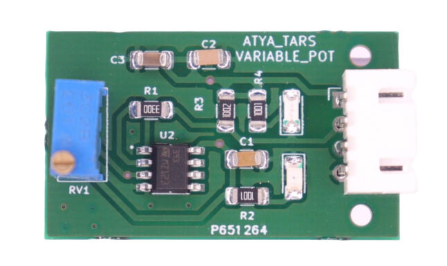
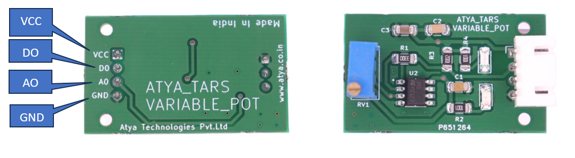
VARIABLE POTENTIOMETER
General Description:
A 10k potentiometer is a type of variable resistor that is used to adjust the resistance in an electrical circuit. The "10k" in the name refers to the resistance of the potentiometer, which is 10,000 ohms (10k ohms). An adjustable potentiometer, 10K Potentiometer Module can open up many interesting user interfaces. Turn the pot and the resistance changes. Connect VCC to an outer pin, GND to the other, and the center pin will have a voltage that varies from 0 to VCC depending on the rotation of the pot.
Working Principle:
A 10k potentiometer module operates using a resistive track with a sliding contact (wiper) that adjusts resistance. The wiper's position determines the resistance between the wiper terminal and one of the other terminals. When the wiper is at one end of the track, the resistance between the wiper terminal and that end terminal is maximum (10k ohms), while the resistance between the wiper terminal and the other end terminal is minimum (0 ohms). Conversely, when the wiper is at the opposite end, the resistance values are reversed. Rotating the knob or shaft alters the wiper's position, changing output voltage or current. This versatility suits applications like volume control, light dimming, and motor speed adjustment.
Specifications:
1. It has a resistance of 10 kilohms.
2. Its dimensions are 18 x 23 x 25 mm (length x width x height).
3. weighs 8 grams.
4. It outputs an analog signal.
5. The operating voltage is +5 volts DC.
Requirements
| S. No. | Component Name | Values |
|---|---|---|
| 1 | Potentiometer | 10k |
| 2 | Male connector Pins | 3 |
| 3 | Knob |
Pin configuration:
| S. No. | Pins | Pin Description |
|---|---|---|
| 1 | GND | Connect to Ground |
| 2 | OUT | Connect to Analog Output Pin |
| 3 | Vcc | Connect to 5V |
Pin Diagrams:
Applications:
1. Volume Control: Potentiometer modules are commonly deployed in audio equipment to control volume levels precisely.
2. Dimmer Control: In lighting systems, these modules find utility in controlling light brightness.
3. Motor Speed Control
4. Sensor Calibration: They play a pivotal role in calibrating analog sensors, guaranteeing accurate and reliable sensor readings across various applications.
5. Thermostat Adjustment: Potentiometer modules are applied in thermostat circuits for temperature control. Because this functionality empowers users to set desired temperatures for comfort and energy efficiency.
For more info: Refer the Datasheets!
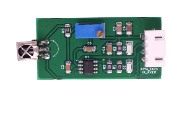
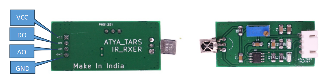
IR RXER
General Description:
An infrared receiver, or IR receiver, is hardware that sends information from an infrared remote control to another device by receiving and decoding signals. In general, the receiver outputs a code to uniquely identify the infrared signal that it receives. This code is then used to convert signals from the remote control into a format that can be understood by the other device. It is the part of a device that receives infrared commands from a remote control.
Working Principle:
An IR receiver can detect bursts of infrared light sent by a common remote controller (like for a television), and then output a pattern of high/low signals to a Propeller I/O pin. This quick tutorial will first show you how to wire up the infrared receiver. Then, you will run a test program that will display the number for the remote button pressed in the Serial Terminal.
Specifications:
1. Receiving angle: 90 °.
2. Working voltage: 2.7 ~ 5.5V.
3. Frequency: 37.9KHz.
4. Receiving range: 18m.
Requirements
| S. No. | Component Name | Values |
|---|---|---|
| 1 | Photodiode | |
| 2 | Resistor | 1k |
| 3 | LED | |
| 4 | Male Connectors | 3 |
Pin configuration:
| S. No. | Pins | Pin Description |
|---|---|---|
| 1 | S | Digital output |
| 2 | VCC | Input Voltage 3.3-5v |
| 3 | GND (-) | Connect to ground |
Pin Diagrams:
Applications:
1. TV.
2. Video machine.
3. Set-top boxes.
4. Digital photo frame.
5. Air conditioner, etc.
For more info: Refer the Datasheets!