

MOTOR DRIVER IC

General Description:
L293D Motor Driver Module is a medium-power motor driver perfect for driving DC Motors and Stepper Motors. It uses the popular L293 motor driver IC. It can drive 4 DC motors on and off, or drive 2 DC motors with directional and speed control. You can connect the two channels in parallel to double the maximum current or in series to double the maximum input voltage. This motor driver is perfect for robotics and mechatronics projects for controlling motors from microcontrollers, switches, relays, etc.
Working Principle:
A motor driver IC regulates the speed and direction of a motor by receiving control signals. It employs power stages, often in an H-bridge configuration, to deliver power to the motor. Pulse Width Modulation (PWM) is commonly used for speed control. Advanced features include current sensing, thermal protection, and feedback mechanisms for precise motor control and safety.
Specifications:
1. Operating Voltage (VDC) 4.5V - 12V
2. Peak Current (A) is 600mA per motor.
3. Generating the PWM signals can be
4. L293D motor driver IC provides a convenient and cost-effective solution.
5. High reliability and long-term stability
6. High signal-to-noise ratio
Requirements
| S. No. | Component Name | Values |
|---|---|---|
| 1 | L293D Motor Driver IC | |
| 2 | Terminal Block | 4 |
| 3 | Resistors | 1k |
| 4 | Capacitors | 10u |
| 5 | Diodes (IN4007) | |
| 6 | Male pin connector | 10 |
| 7 | LED |
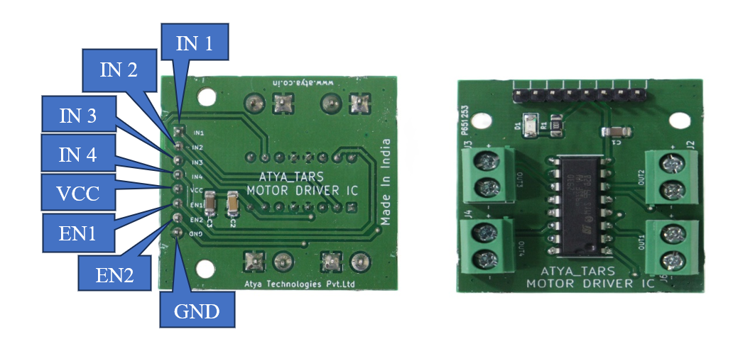
Pin configuration:
| S. No. | Pins | Pin Description |
|---|---|---|
| 1 | IN1 | Input pin |
| 2 | IN2 | Input pin |
| 3 | EN1 | Enable Pin1 |
| 4 | IN3 | Input pin |
| 5 | IN4 | Input pin |
| 6 | EN2 | Enable Pin 2 |
| 7 | VCC | Input voltage 4.5V - 12V |
| 8 | GND | ground |
| 9 | OUT1 | Output pin (Motor o/p) |
| 10 | OUT2 | Output pin (Motor o/p) |
| 11 | OUT3 | Output pin (Motor o/p) |
| 12 | OUT4 | Output pin (Motor o/p) |
Pin Diagrams:
Applications:
1. Home Automation such as curtains, blinds, or garage door openers
2. Electronic Toys such as remote cars, planes, etc.,
3. DIY Projects such as motorized camera sliders, small robots, and CNC machines.
For more info: Refer the Datasheets!