


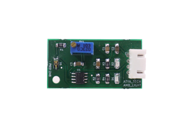
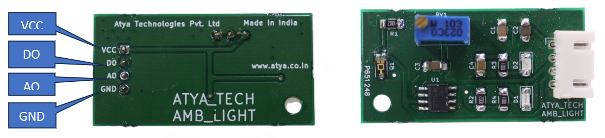
AMBIENT LIGHT SENSOR
General Description:
This CJMCU-TEMT6000 Ambient Light Sensor module uses a special ambient light detector (TMET6000) with a spectral response that closely emulates the human eye. It helps you to detect the light density and reflect the analog voltage signal to the Arduino controller. This sensor is a silicon NPN epitaxial planar phototransistor in a miniature transparent 1206 package for surface mounting. It is sensitive to visible light much like the human eye and has a peak sensitivity at 570 nm. While this device is very sensitive to ambient light, but inhibits the infrared (IR) spectrum, which can provide similar “to the human eye,” the visible spectrum greater responsiveness.
Working Principle:
Being a phototransistor, this sensor acts just like any other NPN transistor -- the greater the incoming light on the Base, the more current that can flow from the Collector to the Emitter. Only light that falls within the visible spectrum (390-700 nm) will alter the Base. Infrared, ultraviolet, or any other light we can't directly see will not affect the sensor.
To make taking light measurements as easy as possible, this sensor has been designed into a voltage divider circuit. The TEMT600 acts as one of the resistors in the divider, and, as the light hitting it changes, so too does the voltage on the SIG pin. To read that voltage, simply connect the SIG pin on the TEMT6000 to any analog-to-digital pin on your microcontroller.
Specifications:
1. AEC-Q101 qualified.
2. High photosensitivity.
3. The maximum current is 20 mA.
4. The power supply mode is within the range of 3.3 to 5 volts.
5. Collector-emitter voltage is 1.5 volts.
6. The wavelength is 570 nm.
7. Detection angle is 60 degrees.
8. Near-Human Eye Spectral Response.
9. Scalable Output Voltage.
10. Adapted to human eye responsively.
11. Lead (Pb)-free reflow soldering.
12. Compliant to RoHS Directive 2002/95/EC and in accordance to WEEE 2002/96/EC.
Requirements
| S. No. | Component Name | Values |
|---|---|---|
| 1 | Resistors | 10k |
| 2 | TEMT6000 (Ambient sensor) |
Pin configuration:
| S. No. | Pins | Pin Description |
|---|---|---|
| 1 | S | Connect to the Analog output pin |
| 2 | G | Connect to ground |
| 3 | V | Connect to 3.3 - 5V |
Pin Diagrams:
Applications:
1. Automotive sensors.
2. Mobile phones.
3. Notebook computers.
4. PDA's.
5. Cameras.
6. Dashboards.
For more info: Refer the Datasheets!
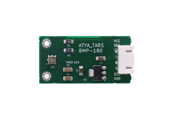
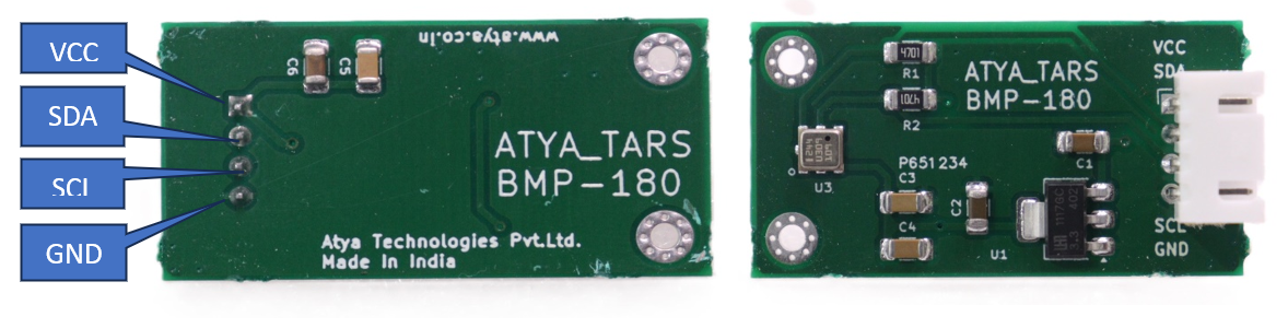
BMP180 (DIGITAL BAROMETRIC PRESSURE SENSOR)
General Description:
BMP180 combines barometric pressure, temperature, and altitude. The I2C allows easy interface with any microcontroller. The onboard 3.3V LDO regulator makes this board fully 5V supply-compatible. BMP-180 can measure pressure range from 300 to 1100hPa (+9000m to -500m relating to sea level) with an accuracy down to 0.02hPa (0.17m) in advance resolution mode. BMP-180 uses piezo-resistive technology for high accuracy, linearity, EMC robustness, and stability for a longer period.
Working Principle:
The BMP180 atmospheric pressure sensor is very simple and its working is based on air weight. BMP 180 atmospheric pressure sensor senses the pressure. The sensor comprises four basic components, a piezoresistive sensor, an analog-to-digital converter, control unit with an E2PROM 12C serial interface. When the air weight or pressure gets changed, the resistance of the piezoresistive sensor also gets changed. Since the value is analog, therefore it would get converted into digital through ADC. After that, the value goes through the control unit, and finally, it is sent to the controller through the 12C interface.
Specifications:
1. The sensor is I2C compatible.
2. It operates within a pressure range of 300 to 1100 hectopascals (hPa).
3. The sensor offers a high relative accuracy of ±0.12 hPa.
4. It can operate on low voltages, with an operating voltage range of 1.3 to 3.6 volts DC.
5. Peak current consumption is 1000 microamperes (µA).
6. Standby current is 0.1 µA.
7. Operating temperature ranges from -40 to 80 degrees Celsius.
Requirements
| S. No. | Component Name | Values |
|---|---|---|
| 1 | Resistors | 1K, 10k |
| 2 | Capacitors | 1μF, 4.7μF, 0.1μF, |
| 3 | BMP180 (Sensor) | |
| 4 | Male connector pins | 4 |
| 5 | Positive Fixed LDO Voltage Regulator | XC6206P332MR (662K) 3.3V 200mA |
Pin configuration:
| S. No. | Pins | Pin Description |
|---|---|---|
| 1 | SDA | Serial Data pin (I2C interface) |
| 2 | SCL | Serial Clock pin (I2C interface) |
| 3 | GND | Connected to ground. |
| 4 | 3.3V | Input voltage |
Pin Diagrams:
Applications:
1. Enhancement of GPS navigation (dead-reckoning, slope detection, etc.).
2. In- and out-door navigation.
3. Leisure and sports.
4. Weather forecast.
5. Vertical velocity indication (rise/sink speed).
For more info: Refer the Datasheets!
BMP280 (BAROMETRIC PRESSURE & ALTITUDE SENSOR)
General Description:
The BMP280 sensor is a high-precision module capable of detecting atmospheric temperature, pressure, and humidity. It supports both the SPI and I2C interfaces and comes pre-calibrated, eliminating the need for additional calibration before use. This is an inexpensive sensor that measures temperature and barometric pressure, but because pressure varies with altitude, we can also use it as an altimeter with an accuracy of about one meter. This is an inexpensive sensor that measures temperature and barometric pressure, but because pressure varies with altitude, we can also use it as an altimeter with an accuracy of about one meter.
Working Principle:
A GY-BMP280-3.3 high-precision atmospheric pressure sensor module works by using a BMP280 sensor from Bosch that can measure both pressure and temperature. The BMP280 sensor has a piezoresistive pressure sensor and a thermistor inside a sealed metal chamber. The piezoresistive sensor changes its resistance according to the pressure applied to the chamber. The thermistor changes its resistance according to the temperature inside the chamber. The module has an integrated circuit that converts the resistance values into digital signals and sends them to the Arduino through either an I2C or SPI interface.
Specifications:
1. Operates within the range of 1.71V to 3.6V - would typically be operated from 3.3V.
2. Operating Temperature: The sensor functions within a temperature range of -40 to +85 degrees Celsius. Full accuracy is achieved between 0 and +65 degrees Celsius.
3. The peak current consumption is 1.12mA.
4. The sensor measures pressure within the range of 300 hPa to 1100 hPa.
5. Accuracy: Between 700 to 900 hPa and 25 to 40 degrees Celsius, the accuracy is ±0.12hPa and ±1.0 meters.
6. Supports both I2C and SPI interfaces.
7. The air pressure sampling rate is 1 Hz.
Requirements
| S. No. | Component Name | Values |
|---|---|---|
| 1 | Resistors | 10k |
| 2 | Capacitors | 1 μF, 0.1 μF |
| 3 | BMP 280 Chip | 1 |
| 4 | Male connector pins | 6 |
Pin configuration:
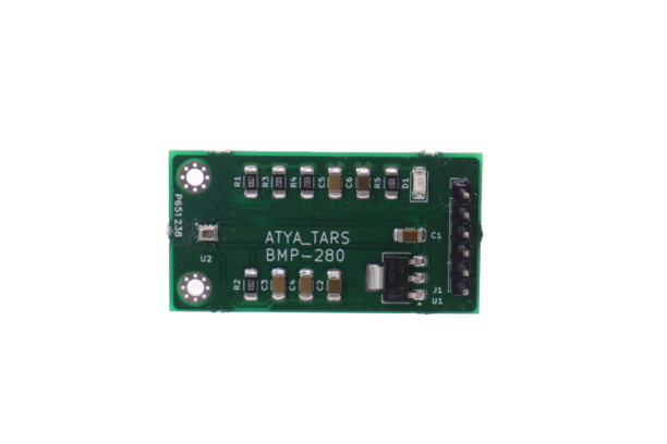
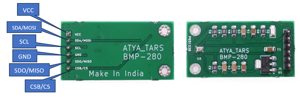
| S. No. | Pins | Pin Description |
|---|---|---|
| 1 | Vcc | Connect to 3.3V supply |
| 2 | GND | Connect to ground |
| 3 | SCL | Serial Clock PIN for I2C and SPI communication. |
| 4 | SDA/MOSI | Serial Data PIN for I2C and Master Out Slave In for SPI Communication. |
| 5 | CSB | CSB pin to GND to have SPI and to VCC (3.3V) for I2C. It's an input to the chip. |
| 6 | SD0/MISO | Serial Data Out / Master in Slave Out pin for SPI Communication . |
Pin Diagrams:
Applications:
1. Enhancement of GPS navigation (e.g. time-to-first-fix improvement, dead-reckoning, slope detection).
2. Indoor navigation (floor detection, elevator detection).
3. Outdoor navigation, leisure, and sports applications.
4. Weather forecast, home weather stations.
5. Health care application (e.g. spirometry).
6. Vertical velocity indication (e.g. risk/sink speed).
7. Handsets such as mobile phones, tablet PCs, GPS devices.
8. Flying toys.
9. Watches.
For more info: Refer the Datasheets!
RAIN SENSOR
General Description:
A rain sensor is one kind of switching device which is used to detect the rainfall. It works like a switch and the working principle of this sensor is, that whenever there is rain, the switch will be normally closed. The rain sensor module/board is shown below. This board includes nickel-coated lines and it works on the resistance principle. This sensor module permits gauging moisture through analog output pins & it gives a digital output while the moisture threshold surpasses.
Working Principle:
Raindrop sensor works on the principle of resistance. The principle is that when there is no raindrop on board, the resistance is high so we can get high voltage according to V=IR. When raindrops are present the resistance is reduced as water is a conductor of electricity and its presence connects nickel lines in parallel so the reduced resistance and there is a voltage drop across it.
Specifications:
1. This sensor module uses good quality double-sided material.
2. Anti-conductivity & oxidation with long-time use.
3. The sensitivity can be adjusted by a potentiometer.
4. For easy installation, it uses bolt holes.
5. It uses an LM393 comparator with wide voltage.
6. The output of the comparator is a clean waveform and the driving capacity is above 15mA.
Requirements
| S. No. | Component Name | Values |
|---|---|---|
| 1 | LM393 (Voltage Comparator) | |
| 2 | Resistor | 150R,1K,10K,100K |
| 3 | Variable Potentiometer | 100K |
| 4 | LED'S | |
| 5 | Male Connector Pin | 6 |
| 6 | Capacitors | 1uF |
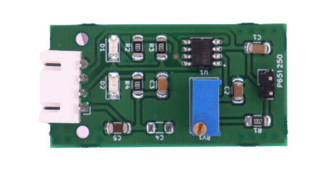
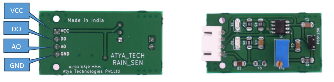
Pin configuration:
| S. No. | Pins | Pin Description |
|---|---|---|
| 1 | VCC (+) | 3.3-5v |
| 2 | GND(G) | Connect to ground |
| 3 | D0 | Digital output pin |
| 4 | A0 | Analog output pin |
Pin Diagrams:
Applications:
1. Irrigation.
2. Automobile industry.
3. Weather Stations.
For more info: Refer the Datasheets!
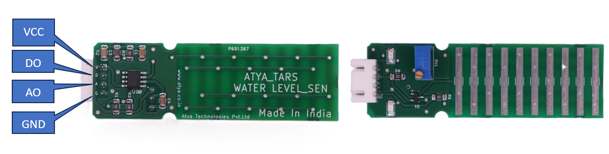
WATER LEVEL SENSOR
--651267-A.png)
General Description:
The water level sensor is a critical component of the water level indicator project. It is designed to detect water levels and provide an output based on the resistance of the water present in the tank. The sensor consists of a series of parallel exposed conductors, acting as a variable resistor. When submerged in water, the sensor's resistance changes, allowing it to indicate different water levels.
Working Principle:
The sensor operates based on the principle of variable resistance. As more water is present in the tank and the sensor is submerged, the conductivity increases, leading to lower resistance. Conversely, less water results in higher resistance. The sensor's analog output is proportional to the resistance, allowing you to determine the water level.
Specifications:
1. The operating voltage range is 3 to 5 volts DC.
2. Maximum operating current is 20 mA.
3. The detecting range of the sensor is 40 x 16 mm.
4. The sensor type is Analog.
5. Operating temperature ranges from -10 to 30 °C.
6. Humidity range tolerated is 10% to 90% non-condensing.
7. Length measures 60 mm, width 20 mm, and height 1.5 mm.
Requirements
| S. No. | Component Name | Values |
|---|---|---|
| 1 | Conducting Plates | |
| 2 | Resistor | 1K,100K |
| 3 | LED | |
| 4 | Transistor (J3Y) | |
| 5 | Male Connector Pin | 3 |
Pin configuration:
| S. No. | Pins | Pin Description |
|---|---|---|
| 1 | GND | Connect to ground |
| 2 | VCC | Connect to 3.3V-5V |
| 3 | S (Signal) | Analog output pin |
Pin Diagrams:
Applications:
1. Can be used in water tanks to control water levels.
2. Water leakage detection.
3. Automatically turn ON/OFF pumps.
4. Can be used in factories, commercial complexes, apartments, home.
5. Fuel tank level gauging.
6. Oil tank level control.
7. Rain Monitoring System.
For more info: Refer the Datasheets!
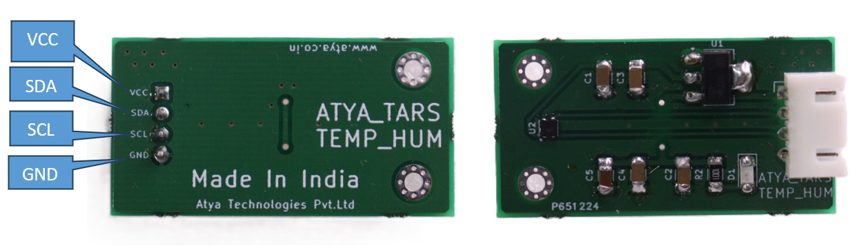
TEMPERATURE AND HUMIDITY
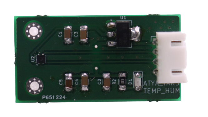
General Description:
The digital sensor measures the changes in humidity and temperature very precisely. Since it's very accurate and the temperature range is wide. The breakout board uses the I2C communication protocol.
Working Principle:
The SHTC3 sensor uses a capacitive humidity sensing element and a temperature sensor to measure humidity and temperature, respectively. It converts these measurements into digital values using internal circuitry. The sensor communicates these values to an external microcontroller or device via an I2C interface.
Specifications:
1. Operating Voltage: 3.3V~5V.
2. Operating Current: 0.45mA.
3. Communication Interface: I2C.
4. Humidity Measurement Range: 0~100%RH.
5. Humidity Measurement Accuracy: ±2%.
6. Temperature Measurement Range: -40~+125℃ (-40 to +275℉).
7. Temperature Measurement Range: ±0.2℃.
8. Response Time: 8s (tau63%).
Requirements
| S. No. | Component Name | Values |
|---|---|---|
| 1 | Resistors | 10k |
| 2 | Capacitors | 100nF,4.7uF |
| 3 | Transistors | 2N7002 (2) |
| 4 | LDO (low dropout voltage regulator) | |
| 5 | SHTC3 (sensor) | |
| 6 | Male connector | 4 |
Pin configuration:
| S. No. | Pins | Pin Description |
|---|---|---|
| 1 | VCC | 3.3-5v |
| 2 | GND | Connect to ground |
| 3 | SCL | Serial clock line |
| 4 | SDA | Serial data address |
Pin Diagrams:
Applications:
1. Can be used in water tanks to control water levels.
2. Water leakage detection.
3. Automatically turn ON/OFF pumps.
4. Can be used in factories, commercial complexes, apartments, home.
4. Fuel tank level gauging.
5. Oil tank level control.
6. Rain Monitoring System.
For more info: Refer the Datasheets!
SOIL MOISTURE SENSOR
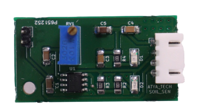
General Description:
The soil moisture sensor is a sensor used to measure the moisture of soil that is in the active root. Mainly used in the agriculture sector, gardening, and research purposes.
Working Principle:
This sensor primarily uses capacitance to measure soil moisture content (permittivity). The functionality of this sensor can be performed by inserting this sensor into the soil and reporting the moisture content status of the soil in percentage. Soil moisture content may be determined via its effect on the dielectric constant by measuring the capacitance between two electrodes implanted in the soil. Where soil moisture is predominantly in the form of free water (e.g., in sandy soils), the dielectric constant is directly proportional to the moisture content.
The probe is normally given a frequency excitation to permit measurement of the dielectric constant. The readout from the probe is not linear with water content and is influenced by soil type and soil temperature. Therefore, careful calibration is required and the long-term stability of the calibration is questionable.
Specifications:
1. Integrated with LM393 comparator module.
2. Dual output analog and digital.
3. It has to fix bolt holes for easy mounting.
4. Operating voltage is 3.3 - 5v.
5. Current flow is 20mA.
Requirements
| S. No. | Component Name | Values |
|---|---|---|
| 1 | LM393 (OP-AMP) | |
| 2 | Resistor | 150R,1K,10K,100K |
| 3 | Variable Potentiometer | 100K |
| 4 | Capacitors | 104 |
| 5 | LED'S | |
| 6 | Male Connector Pin | 6 |
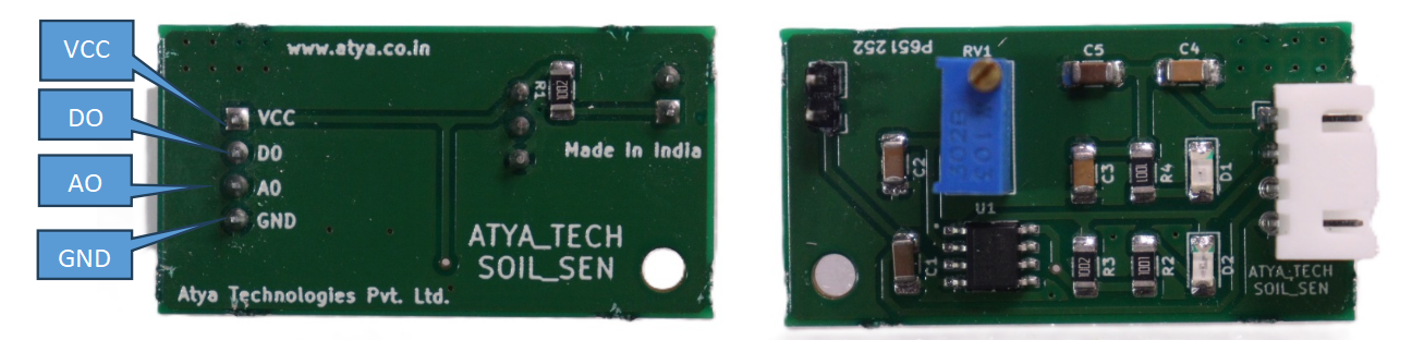
Pin configuration:
| S. No. | Pins | Pin Description |
|---|---|---|
| 1 | VCC (+) | 3.3-5v |
| 2 | GND(G) | Connect to ground |
| 3 | D0 | Digital output pin |
| 4 | A0 | Analog output pin |
| 5 | + | Connect to soil sensor |
| 6 | - | Connect to soil sensor |
Pin Diagrams:
Applications:
1. Agriculture.
2. Landscape irrigation.
3. Research.
4. Gardening.
For more info: Refer the Datasheets!